DIGITAL - COUNTER
On the rising edge of the clock pulse, D is copied to Q.
Since NOT Q is connected to D, the data is inverted on each rising edge.
This has the effect of dividing the frequency by two.
Since NOT Q is connected to D, the data is inverted on each rising edge.
This has the effect of dividing the frequency by two.
- The D Type Flip Flop is used in Binary Counters.
- Here is the circuit for a one bit counter.
- This can also be used as a frequency divider. It divides the frequency by two.
- The UP in Up Counter is because the counter counts normally with increasing numbers like 0, 1, 2, 3 etc.
- The output of this circuit is high for 50% of the time and low for 50% of the time.
- This is a 1:1 mark space ratio.
- This is true whatever the mark space ratio of the clock pulses.

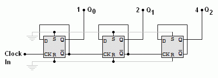
Three Bit Binary Up Counter
This divides the frequency by 8 (or by two three times).
On the rising edge of the clock pulse the counter output increases by one.

The output from the left flip-flop is worth one (least significant bit LSB).
The output from the middle flip-flop is worth two.
The output from the right flip-flop is worth 4 (most significant bit MSB).
The output from the middle flip-flop is worth two.
The output from the right flip-flop is worth 4 (most significant bit MSB).
Here is a timing diagram for the three bit counter.

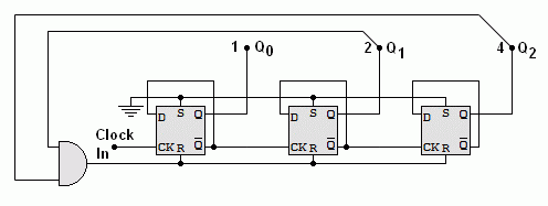
Modulo N Up Counter
This is a counter that resets at a chosen number. For example a two digit decimal counter, left to its own devices will count from 00 to 99. This is not much use for a clock unless you have 100 second minutes. To fix the problem, the counter must go from 00 to 59. This is achieved by detecting a 6 in the left hand digit and using it to reset the counter to zero. This would be a Modulo 6 Counter or 60 if you included both digits.
dModulo 6 Counter - Counts from 0 to 5

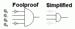
The circuit above detects a six or 0110 in binary. You could use the fool proof circuit but in fact the simpler circuit works too because the 0110 pattern only occurs once between 0 and 9 in decimal numbers. The output is used to reset the counter.
